I was looking through a drawer the other day, and I discovered my old Gameboy Advance, and my favourite game of the time: Pokémon – Gold Edition. This was my first game in the Pokémon series I owned, and I had collected quite a few rare Pokémon in the time I played it. I decided to load it up, but sadly when I did, I discovered the worst had happened.
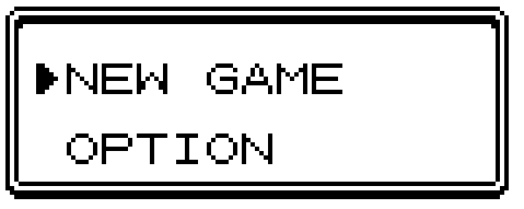
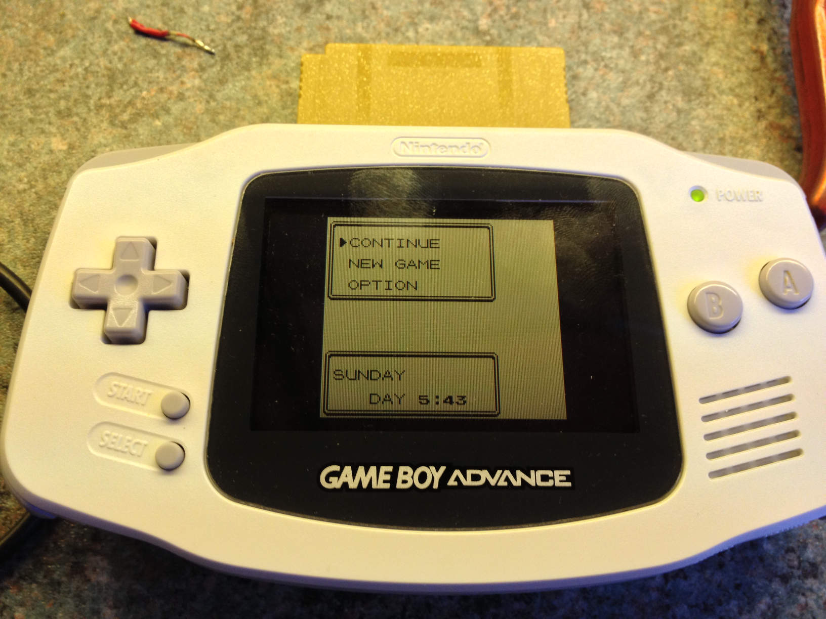
The menu of Pokemon Gold minus the Continue option
The “Continue” option was missing which could only mean one thing. The battery that powers the volatile memory chip had run out.
It appears the between the launch of the original Gameboy in 1989 until the end of the Gameboy Color’s game development in 2002, the design of the cartridges have remained unchanged. Back in 1989 it would have been a lot cheaper for the systems to use volatile memory (that requires power to remember information) and a battery, than use other forms of memory such as an EEPROM (which was used in Gameboy Advance cartridges). When games like the second generation Pokémon games and (in Japan) Keitai Denjū Telefang started using a real time clock to make the games act differently at different times of the day, the little battery was not only being slowly drained by the memory, but the clock, which meant the battery life was shortened considerably more.
I confirmed this by starting a new game, saving once I got into game play. After powering off the Gameboy and powering it on again, the continue button was still missing.
Taking apart the cartridge wasn’t too difficult. Nintendo opted to use a security screw attempt to stop people open them up, but by using a pair of pliers, I was able to grip the top of the screw and turn the cartridge itself to loosen the screw. Once the screw was removed, the front of the cartridge (the bit with the picture on it) slides downwards and lifts off revealing the internal PCB.
At this point, I wanted to confirm that the battery was, indeed, flat.
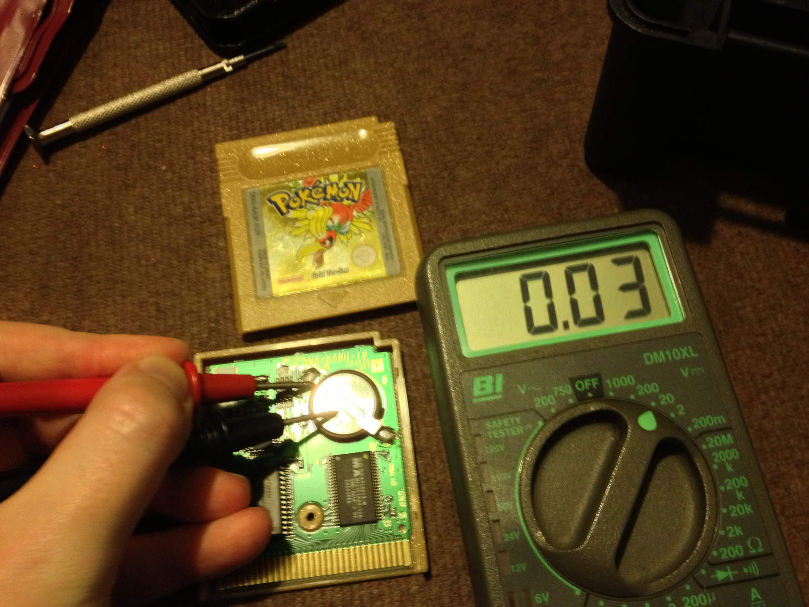
The 3V battery reading a dismal 0.03V (Check out the one handed skill!)
There was no doubt by this point that it was the battery that was to blame. The battery in question was a CR2025 button cell which, when new, will read a little over 3 Volts, but after 13 years in this cartridge, had flattened itself giving a rather pathetic reading of 0.03 Volts.
Removing the battery was simple enough, my electric solder sucker was placed onto the two solder pads and, after removing the solder, the battery pretty much just lifted away from the board.
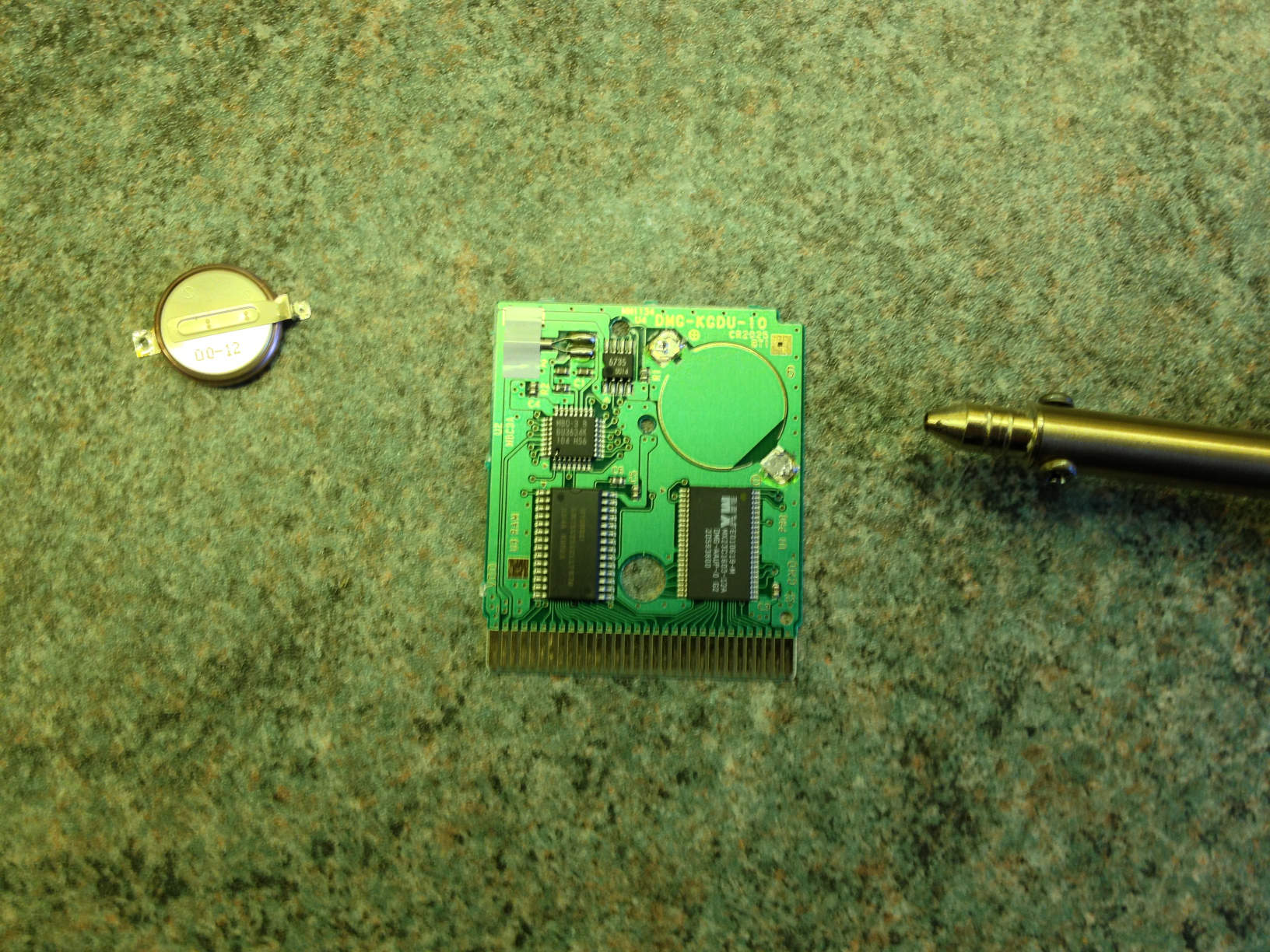
The battery removed from the game’s PCB
The most challenging part next.
I had a look around my house, and was unable to find a space CR2025 button cell lying around. But, being a computer enthusiast, I had plenty of the larger CR2032 button cells commonly used on PC motherboards. This battery is just as wide as the one that was in the cartridge, but a little taller. I figured it’d be tight, but it should fit. The side effect would be that it should last a bit longer than the original cell.
The other problem is that, whilst the old battery had lugs to solder to the board, the replacement did not. I decided to do the controversial thing and attempt to connect the battery by soldering wires directly to each side of the battery and connecting those to the pads on the PCB.
At this point, I’m going to discourage anyone from doing the same without being prepaid for the worst possible outcome. The button cells used here are lithium based, and if heated too much can potentially explode! Do NOT attempt to do this unless you’re well prepared. If you don’t feel confident with this method, proper CR2025 cells with lugs can be purchased online.
I got some thin insulated wire and soldered this directly to the negative side of the cell, I then wrapped the battery in a damp cloth and let it cool. I flipped the cell over and soldered about 3 strands of uninsulated wire to this side (the thinner the wire, the better, as this side of the battery needs to sit flush to the board (especially when using the thicker battery). I wrapped the battery in a damp cloth again until it was cool.
Once the two wires were in place, I measured the voltage of the battery through the wires to make sure it was still reading just over 3 Volts.
I then faced the battery positive side down and soldered the positive (uninsulated) wire to the solder pad on the top of the board. At this point I put a bit of insulator tape on the bottom half of the battery, so it wouldn’t short out on the other pad as it might cause an explosion and, if it didn’t, it would certainly erase any save games. After laying the battery down on the board, I soldered the negative wire from the top of the battery to the bottom solder pad.
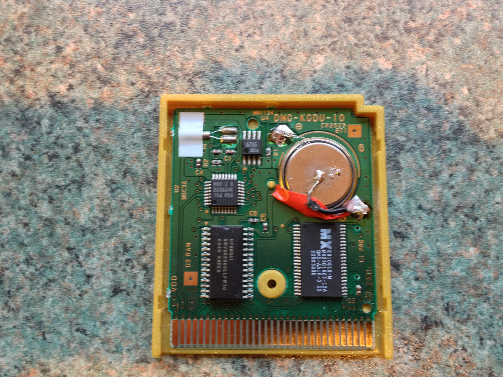
Not the neatest job, but firmly connected.
All that was left to do was pop the cover back on (which was a tight fit, with only a little bit of bulging of the case) and test it out.
After saving a new game, the continue option returned.
After saving a new game and power cycling the Gameboy, I was greeted with the Continue option.
It’s a shame I had to lose my 13 year old game I had been working on since I was 10, I think that means I can safely say my childhood has officially ended! 🙁
But nonetheless, replacing the battery in your old game is a fun little project to do on a boring rainy day, if there was only a way to keep power to the chip whilst replacing the battery….
2013-03-24: Turns out, there IS a way to retain the save information whilst switching batteries.
Cheers